Review Article - European Journal of Applied Engineering and Scientific Research ( 2018) Volume 6, Issue 2
Energy is prime need for the man, initially the use of Energy was limited but with the civilization the consumption of energy for different purposes increased. The sun was fulfilling all the energy needs of human being either directly or indirectly and man was using only renewable sources of energy. The most important being solar energy, which will focus our attention solar energy, is a large, inexhaustible source of energy. It is one of the most promising sources of non-conventional energy sources. Solar energy can utilize by various ways, photovoltaic (PV) convention has its own importance. By means of solar cells light can be directly converted into electricity using PV effect. In future solar cells become an important source of power for providing electrical energy for localized use, particularly in remote areas. In view of the above discussion, to get the maximum conversion efficiency of Amorphous silicon a-Si:H based solar cells, it is necessary to minimize the losses due to the shading of metal grid on the top of the solar cell surface and to increase the absorption of incident photon energy. This will require a conducting and transparent material having wide band gap. A survey of the literature shows that the ZnO semiconductor is found to a suitable material with wide band gap (>3 eV) having high transparency in visible region and high electrical conductivity. Furthermore, the aim of present study is to understand the deposition technique (spray pyrolysis) and to optimize the process parameters so as to get best opto-electronic properties of ZnO thin films.
Organo metallic, Temperature, Photon energy
It is a chemical vapour deposition technique. Formation of the thin film in this technique is due to the heterogeneous reactions taking place at or near the substrate surface. Spray pyrolysis process involves spraying of solution containing soluble organo-metallic of desired compound onto heated substrate. For this purpose, the compound is dissolved in mixture of water and methanol, and then sprayed over a hot substrate under controlled conditions, which result in the transparent conductive film [1-4].
Various process parameters
In spray pyrolysis process an aqueous solution of inorganic or organo metallic compound is spray on a hot substrate then the fine droplets decomposed to give the desired coating. Now it is seen that even though the process is very simple the optimization of process parameters is quite laborious and difficult. It is due to large number of process parameters involved. The various process parameters involved in the chemical spray pyrolysis are:
Air flow rate
In general, compressed air is used as carrier gas in pyrolysing the sprayed solution. The flow rate of both solution and the air are strongly dependent on the geometry of the coating chamber, particularly the furnace and on the nozzle substrate separation [5]. The airflow rate (AFR) used affects the size and velocity distribution of the droplets more significantly affects the solution spray rate turbulence and lateral wind and force of the impinging droplets at the substrate. Films deposited at lower AFR are non-uniform and foggy while high AFR yield films of unexpected resistivity and transmission.
Nature and temperature of the substrate
The nature of the substrate is one of the important process parameter controlling the opto-electronic and structural properties of the films. The lower temperature grows the amorphous films while high temp deposition results in polycrystalline film. When the substrate temperature is increased the grain size increases and preferred orientation effects are found to decrease [6]. Varieties of nature substrate are used for coating such as glass, polymers and metal foil. The usual optimum temperature for spray pyrolysis technique is in the range between 200-350°C. Substrate temperature affects the structural properties of a film. At low temperature, the decomposition reaction is not completed and hence doesn’t result into desired composition in the film.
Spray nozzle diameter
The Spray nozzle diameter determines the droplet size and hence the uniformity of a film. As a consequence, the electro optical properties of deposited film are also affected. If droplets are too big, it causes cracking of the hot substrate due to high thermal shock. If the droplets are too small they get evaporated before reaching the substrate and results in powder deposition. In this way for the uniform deposition and substrate adherent film, size of the droplet plays dominant role. Nozzle diameter 0.4 mm to 0.8 mm is suitable for spray deposition [7].
Nozzle to substrate distance
The velocity with which droplet strikes the hot surface depends on journey time and covered distance for less travel time gives highly resistive and incomplete, oxidized thin films. While travel large time droplets evaporate before reaching the substrate yields poor deposition. Hence, nozzle to substrate distance should be optimized. Near about 30 cm distance yield better films.
Volume of sprayed solution
Thickness, electrical conductivity and visible transmission of the film are interrelated. The thickness of the deposited film is proportional to the volume of the solution sprayed. Large quantities of spray solution results in thick film consequently improve the electrical conductivity but loose visible transparency and vice versa.
Geometry of the deposition apparatus
Geometry determines the uniformity of films deposition over large area. Spray stream is decided by geometry of spray unit. The angle of incidence of the spray stream when normal to the substrate gives improved good conductive film than of inclined spray stream to the substrate.
Composition of sprayed solution
Water is the most convenient oxidizing agent for TCOs. But it is usually to dilute solution with alcohol, the lost convenient being methanol or ethanol. The use of spray pyrolysis technique for the preparation of TCO thin film requires a soluble compound that after spraying in solution form onto a hot substrate can decompose into reaction as thin film forms. There are number of compound available but the suitable compound is that which fulfils the required conditions such as:
• Decomposition reaction leading to the formation desired coating should be thermodynamically favourable so that residue of the reactant will not be left behind in the deposited material.
• The products of the decomposition reaction other than the desired one (ZnO) should be volatile so that they can easily out.
• Decomposition temperature should not be very high.
Based on this critical zinc acetate is preferable over its other compounds such as halides, nitrides, etc. The low surface tension and high vapour pressure of methanol or alcohol enables the formation of fine droplets. The nonstoichiometry and pin hole free uniformity of the film governed due to dilute of aqueous solution by methanol or alcohol act as reducing agent.
Determination of thickness
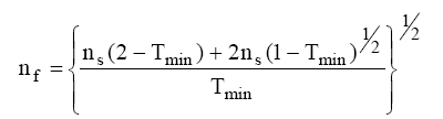
The value of film material refractive index (nf) can be deduced for the wavelength at the minimum of transmission, λmin:
Knowing refractive indices nf, we can use the pattern of transmission with successive minima and maxima to evaluate the thickness (t) of the film.
By taking into account of the oscillations observed in the transmission spectrum due to interference phenomenon (two maxima or minima) in the visible region. The thickness of the films were deduced using the formula proposed by Manifacier as:
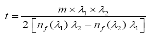
Where nf (λ1) and nf (λ2) are refractive indices of the film at wavelengths λ1 and λ2 and m is the number of oscillations between two successive minima at wavelengths λ1 and λ2 [8-13].
Determination of band gap
If we know T and R then we can easily calculate the absorption coefficient (α) of the given material using the relation [8].
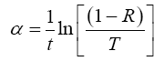
Where, (t) is the thickness of film.
The band gap (Eg) of the material is given by the relation:
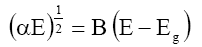
Where, B=Constant
E=hν
E=Energy of photon radiation
h Planck’s constant
ν=Frequency of incident photon radiation
Plot a graph between (αE)1/2 versus incident photon energy hν. The extrapolated straight line on x-axis gives the band gap of the material. The nature of the graph is as shown in Figure 1:
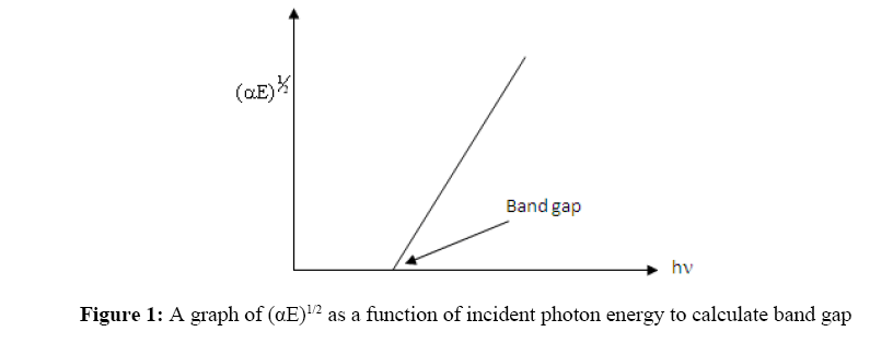
Figure 1: A graph of (αE)1/2 as a function of incident photon energy to calculate band gap
In the present work ZnO thin film were prepared by spray pyrolysis method from 0.5 M, 70 ml aqueous solution of zinc acetate and methanol. Few drops of acetic acid were added to improve the clarity of the solution as shown in Table 1. All films were deposited on a soda lime glass substrate. The substrate temperature was kept constant at 450°C. The carrier gas flow rate is varied in the range 9 LPM to 14 LPM. The nozzle to substrate distance and nozzle diameter were kept constant. The films are allowed to cool to room temperature and then taken out for characterization [9-11].
| Solvents used | De-ionized water and Methanol Carrier gas Compressed air |
|---|---|
| Nozzle-to-substrate distance | 32 cm |
| Nozzle diameter | 0.01 cm |
| Carrier gas flow rate | 9-14 LPM (liter per minute) |
| Substrate temperature | 250°C-450°C |
| Molarity of starting solution | 0.5 M |
| Quantity of precursor solution | 70 ml |
| Amount of Zinc acetate | 7.67 gm |
| Amount of water | 52.5 ml |
| Amount of Methanol | 17.5 ml |
| Time of deposition | 60 min |
Table 1: Deposition conditions for ZnO films
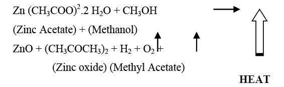
Chemical reaction
The equilibrium chemical reaction can be written as:
Variation of deposition rate
The thickness of the film plays a crucial role in both electron transport properties as well as optical properties. In the present work films were deposited at fixed time period and deposition rate is calculated from the time period. The thickness of the film was determined from the UV-Visible spectroscopy, the Figure 2 shows the variation of deposition rate as function of air flow rate [11,12].
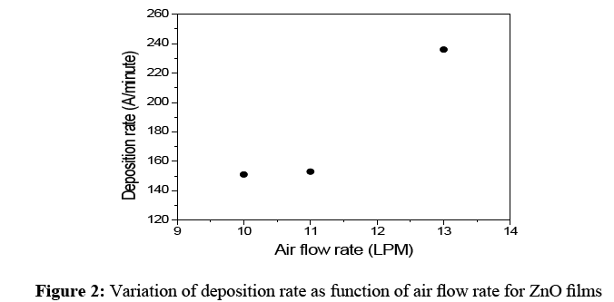
Figure 2: Variation of deposition rate as function of air flow rate for ZnO films
As seen from the figure, the deposition rate increases with increase in air flow rate. The increase in deposition rate with increase in air flow rate can be attributed to the impinging speed of spraying solution [14]. At low air flow rate, the impinging speed of spraying solution is low. As result, the amount of Zn atoms reaching the hot substrate is also low. Therefore the deposition rate is small at lower air flow rate. With increase in air flow rate, the impinging speed of spraying solution increases [13-15]. This increases the amount of Zn atoms reaching the hot substrate. Consequently, deposition rate increases with increase in air flow rate.
Structural properties
It is generally observed that the ZnO films deposited by spray pyrolysis show a high degree of preferential orientations of grains. The x-ray diffract gram of ZnO films deposited at air flow rate 10 LPM precursor solution is shown in Figure 3.
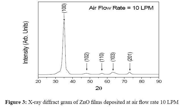
Figure 3: X-ray diffract gram of ZnO films deposited at air flow rate 10 LPM
As seen from x-ray diffract gram the preferred growth of ZnO planes can be controlled by air flow rate of the precursor solution. We found that all films were polycrystalline in nature and corresponding x-ray diffraction spectra fit to a ZnO hexagonal wurtzite structure. It is observed that all ZnO films have strong preferred orientation along (100) direction and its intensity increases with increase in air flow rate of the precursor solution. The other orientations (102), (110), (103) and (201) were also observed, however their intensities are relatively less than the peak (100) and do not get modified by the air flow rate of the precursor solution [16-18].
The variation of average crystallite/grain size estimated using x-ray diffraction spectroscopy for ZnO films deposited at different air flow rates is shown in Figure 4. As seen from the figure, average crystallite size remain constant (200 Å) up to air flow rate of 12 LPM and it suddenly increases to 324 Å for air flow rates 13 and 14 LPM.
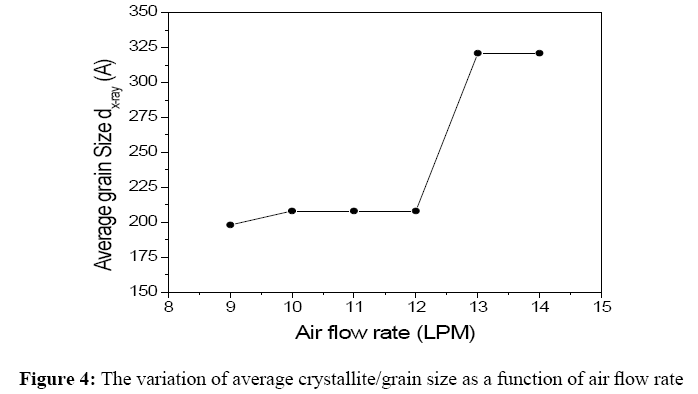
Figure 4: The variation of average crystallite/grain size as a function of air flow rate
UV-Visible spectroscopic analysis
The optical transmittance at normal incidence and spectral reflectance of ZnO films were recorded with double beam spectrophotometer (Hitachi 330 model) in the UV-VIS-NIR in the region 300 nm to 2000 nm [19,20]. The thickness of the ZnO films has been reduced from the observed oscillations in the transmission spectra. Also the optical band gap of the ZnO films have been deduced using the transmittance (T%) and reflectance (R%) data. The typical UVVIS- NIR spectrum of ZnO films deposited by sprayprolysis technique is shown in Figure 5.
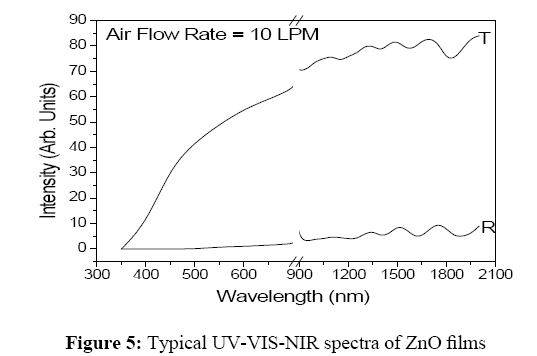
Figure 5: Typical UV-VIS-NIR spectra of ZnO films
As seen from the figure the average transmittance of the film is around 70-75%. The variation of band gap estimated using UV-Visible spectroscopy for ZnO films deposited at different air flow rates is shown in Figure 6.
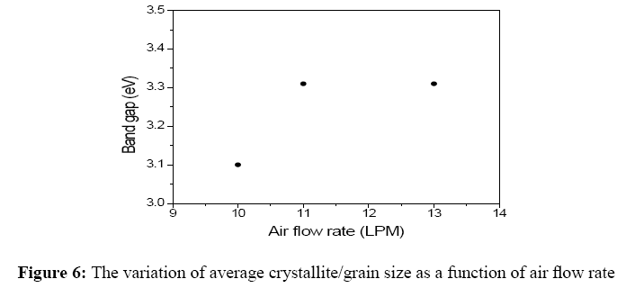
Figure 6: The variation of average crystallite/grain size as a function of air flow rate
As seen from the figure, for low air flow rates (below 10 LPM) the estimated band gap is 3.1 eV and it increases as well saturates to 3.31 eV for the films deposited at higher (above 10 LPM) air flow rates. The change in band gap can be attributed to increase in crystallite size with increase in air flow rate as shown in Figure 6.
Electrical properties
Figure 7 shows the variation in electrical properties with the air flow rate of precursor solution.
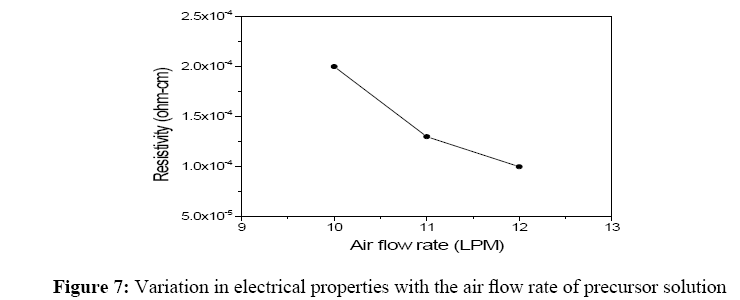
Figure 7: Variation in electrical properties with the air flow rate of precursor solution
As seen in the Figure 7 the electrical properties of ZnO thin films strongly depend on the air flow rate of precursor solution. The resistivity decreases with increase in air flow rate of the precursor solution. The decrease in resistivity with increase in air flow rate can be attributed to the increase in regular lattice sites available for Zn atoms. Furthermore the improved grain size with air flow rate can also be attributed to decrease in resistivity of ZnO thin films [18-23].
Without intermittent and with intermittent ZnO films: Deposition and characterization
Zinc Oxide thin films were deposited by spray pyrolysis technique on soda lime glass at different substrate temperature (350°C to 500°C), air flow rate (8 LPM-12 LPM) and different composition and concentration of the starting solution. The deposited films were polycrystalline in nature at higher substrate temperature. The present chapter describes the deposition and characterization of opto-electrical, structural properties of Zno films with and without intermittent [24,25]. As compared to other deposition techniques, pyrolytic deposition of transparent conducting oxide films is relative inexpensive in terms of equipment cost and is quite simple. However, many deposition parameters are involved and they are mutually dependent on each other. However, to study the effects of any one of these, the remaining others were kept constant. Hence, the optimization of deposition parameters becomes more complicated. To obtain optimum quality film, all of these parameters were optimized on criteria of figure of merit basis and then controlled. The evaluation of deposited thin film, as transparent conductive coating is necessary because under optimum deposition condition visible transmittance and electrical resistivity depend significantly on film thickness.
The electrical resistivity decreases with increasing film thickness however it decreases the transparency. To minimize this simple ratio of average visible transmission to the sheet resistance is used. This leads to optimization of process parameters to obtain excellent quality of transparent conducting films.
During the optimization of process parameters, all films were studied in view of their electrical, optical and structural properties.
Experimental (without intermittent ZnO films)
The un-doped ZnO films prepared by thermal decomposition of zinc acetate Zn(CH3COO)2 2H2O aqua solution on a soda lime glass substrate via spray pyrolysis technique [4-10]. The decomposition conditions for the synthesis of undoped ZnO films without intermittent, used in the present study are Spray parameters Process parameters are shown in Table 2.
| Solvent | De- ionized water, Methanol |
|---|---|
| Substrate temperature | 350°C-500°C |
| Air flow rate | 8l pm-12l pm |
| Concentration of zinc acetate | 0.1-0.5 M |
Table 2: Spray parameters process
The starting solution consisted of zinc acetate dissolved in methanol is sprayed into soda lime glass substrate. The substrate temperature is varied from 350°C-500°C, at an interval of 50°C. The molarity of sprayed solution is varied from 0.1 to 0.5 M at an interval 0.05 M by changing the amount of zinc acetate dissolved in methanol. Each molar solution is sprayed at various air flow rate 8 LPM-12 LPM at an interval of 1 LPM [22-27].
In future, improved transparent conducting oxide films are certain to be required for various applications. Thus, there will be inevitably be a need for transparent conducting oxide films of superior properties with the continued development of the opto-electronic devices. The data presented here are mainly representative and shows that chemical spray pyrolysis technique can be used to produce device quality ZnO films depending upon their applications.
The transparency and electrical resistivity of ZnO films we have obtained is ∼75% and ∼0.13 × 10⁻³ ohm-cm, respectively. These values are not suitable for their use in a-Si:H based solar cells. In order to improve the transparency and electrical resistivity one has to dope these films with suitable impurities like Al, B, F or Cd. One should try to obtain doped ZnO films with high conductivity without scarifying the optical transparency. Furthermore, these ZnO films must be exposed to hydrogen plasma and their stability should be checked in presence of hydrogen plasma.